
Operator Manual
Latest Version

Older Versions
Unboxing
Move the TF5 out of the transport crate properly
Latest Software & Tools
Click to expand
Required files and tools
Latest Version (2.3.3)
The following tools are required for this:
- PEAK CAN USB-Adapter
- Laptop
- Softwarepaket 2.3.3 consisting of:
- PEAK CAN Driver
- Maintenance Tool IFM
- ParaTool 4 TowFLEXX
- Update Files for 2.3.3
- Optional PEAK CAN Viewer
- empty USB Thumbdrive
- USB hub (if laptop has less than two USB ports)
Changelog 2.3.3
- via the radio remote control it is now possible to control whether the magnetic brakes of the tug are released when lifting and lowering the lifting platform (standard setting for all units before 2.3.3), or if these remain locked in order to be able to ensure a safe stand when lifting or lowering even on slight slopes.
- The NPS (Nosewheel Protection System) can now be activated and used via the parameter setting (parameter 57)
Installation Guide 2.3.3
The following steps must be followed to install the update correctly:
- Download Softwarepackage HERE
- Install the PEAK System Driver from the folder “1”
- Install the Maintenance Tool from the folder “2”
- Restart the Computer
- Connect empty USB stick to the Computer
- Copy files from folder “4” (20210615_TOWFLEXX_TF5.5_2.3.3) (without subfolder) to USB stick
- Switch off TF5 and remote control and connect PEAK CAN USB adapter to tug (CAN1 slot) and computer, disconnect other systems connected via CAN ports and connect blind plug back to the CAN interface (if needed).
- Switch on TF5 and Remote Control
- Start the ParaTool (important: application must be started from the folder with “Encoder.ini” and “PCANBasic.dll”
- Read out parameters via “READ” button and define name (please use serial number here for overview)
- Save parameters locally on the computer and send them to “support@towflexx.com”.
- Click on “Update_v2.3.3.bat” on the USB stick
- In the window that pops up, type in “NPS” and confirm with Enter.
- Depending on the model, the next step is to select the correct CAN bus option
- For older TF5.4 please type 1 and confirm with Enter
- For current TF5.5 please type 2 and confirm with Enter
- If all drivers and tools are installed correctly, the update will now start (duration approx. 1-2 minutes).
- At the end, you should see two status indicators in percent, showing a value between 95%-100%
- (if the value is not 100% at the end, this is not a problem, the update is still installed correctly)
- Finally, carry out a complete restart of the unit and the remote control.
- Open ParaTools again and read out the parameters via “READ”. If the first lines read IFM version 2.3.3, the update has been installed correctly.
- Disconnect PEAK CAN USB Adapter
- If no additional system such as the NPS is connected via the CAN ports, the blind plugs must be reconnected and tightened, otherwise Error 1-1 is displayed and the unit is not ready for operation.
Install Software Update
In this 30 minute training video, we cover all the important basics that would also be included in an on-site training session. Starting with the first move out of the transport box, driving functions as well as emergency settings, the TF5 training video covers all topics that every user should be familiar with before the first use. Currently an English and a Spanish version are available. If you own a TF5 and are therefore entitled to access this premium video, please contact us if you need the corresponding password.
English Version

Password required
Spanish Version
Password required
Emergency Settings
Emengency Winch Release
Emergency Brake Release
Training
Deactivate Deadman
Remote Control
Adjust Nosewheel Adapters
Capture & Release an Aircraft
Service & Maintenance
Replace a Castor Wheel
Realign the Gate
Download Maintenance Schedule
| Error Code | Description |
| 04-42 | No SPS available, internal error code of the drive systems |
| 04-60 | No SPS available, internal error code of the drive systems |
| 04-96 | No SPS available, internal error code of the drive systems |
| 04-C9 | No SPS available, internal error code of the drive systems |
| 16-06 | No SPS available, internal error code of the drive systems |
Troubleshooting
If one of these errors appears, first switch off the unit completely (turn key switch and press eStops). Wait 1 minute and switch the unit back on again.
| Error Code | Description |
| 1-1 | Emergency stop pressed |
Troubleshooting
Either one of the two emergency stops on the TF5, or the emergency stop on the radio remote control was pressed.
All emergency stops are released, but error still appears?
On the front side of the eCube there are programming interfaces marked CAN1 and CAN2. If no additional system such as the NPS is connected there, blind plugs (dummy plugs) must be connected to these ports, otherwise this has the same effect as actuating an emergency stop and error code 1-1 is displayed.
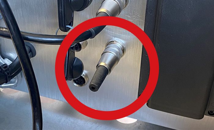
TF5.5 Blindplug
| Error Code | Description |
| 1-2 | Remote control not in default position |
Troubleshooting
When switching on the TF5 for the first time, all switches on the radio remote control must be in their default position. This is to prevent an unintended setting from being active, causing uncontrolled movements that could result in damage to the tug, aircraft or personell. The default settings can be found in the user manual under “4.1 – Radio remote control”.
| Error Code | Description |
| 1-3 | No connection to radio remote control possible |
Troubleshooting
| Error Code | Description |
| 1-5 | Joystick error K1A/B (left) |
Troubleshooting
There is an error with the left joystick of the remote control, which is responsible for the forward and backward movement.
- Check whether the joystick is blocked
- Restart the radio remote control and check if the error still remains
- Move the joystick several times in both directions, then restart the remote control again and check if the error still remains.
If these steps are not successful, the joystick must be replaced.
| Error Code | Description |
| 1-6 | Joystick error K3A/B (right) |
Troubleshooting
There is an error with the right joystick of the remote control, which is responsible for the steering movement.
- Check whether the joystick is blocked
- Restart the radio remote control and check if the error still remains
- Move the joystick several times in both directions, then restart the remote control again and check if the error still remains.
If these steps are not successful, the joystick must be replaced.
| Error Code | Description |
| 1-7 | Emergency stop error |
Troubleshooting
There is an error with the connection of an emergency stop switch.
| Error Code | Description |
| 1-11 | Release of an emergency stop confirmed |
Troubleshooting
This error indicates that an emergency stop switch was recently pressed. Error 1-11 always appears when the unit is switched on again and an emergency stop has been pressed beforehand.
Both emergency stops on the tug are pulled, yet error 1-11 appears?
Make sure that the emergency stop on the radio remote control is also pulled. This must be turned slightly before it can be pulled up and thus be deactivated.
| Error Code | Description |
| 1-12 | External emergency stop actuated (only for units with special EE certification) |
Troubleshooting
This error indicates that an emergency stop switch was recently pressed. Error 1-11 always appears when the unit is switched on again and an emergency stop has been pressed beforehand.
Both emergency stops on the tug are pulled, yet error 1-11 appears?
Make sure that the emergency stop on the radio remote control is also pulled. This must be turned slightly before it can be pulled up and thus be deactivated.
| Error Code | Description |
| 1-20 | The tug is charging and cannot be moved |
Troubleshooting
The tug is still connected to a power source and is being charged, the drive-away protection is activated
| Error Code | Description |
| 2-8 | No CAN bus signal ACE2 2μ Master motor right |
Troubleshooting
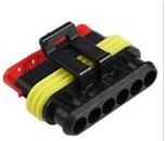
- Check the 6-pin superseal connector of the drive motors
| Error Code | Description |
| 2-9 | No CAN bus signal ACE2 2μ Slave motor right |
Troubleshooting
- Check the 6-pin superseal connector of the drive motors
| Error Code | Description |
| 2-10 | No CAN bus signal ACE2 2μ Master motor left |
Troubleshooting
- Check the 6-pin superseal connector of the drive motors
| Error Code | Description |
| 2-11 | No CAN bus signal ACE2 2μ Slave motor left |
Troubleshooting
- Check the 6-pin superseal connector of the drive motors
| Error Code | Description |
| 2-16 | No CAN bus signal from remote control receiver |
Troubleshooting
| Error Code | Description |
| 2-24 | No CAN bus signal ACE2 Combi 2μ Master |
Troubleshooting
| Error Code | Description |
| 2-25 | No CAN bus signal ACE2 Combi 2μ Slave |
Troubleshooting
| Error Code | Description |
| 3-1 | SPS: Voltage low |
| 3-2 | SPS: Voltage low |
| 3-3 | SPS: Voltage low |
| 3-4 | SPS: Voltage low |
Troubleshooting
| Error Code | Description |
| 3-10 | Turntable synchronization: deviation between drive and turntable too high |
Troubleshooting
| Error Code | Description |
| 3-11 | Turntable synchronization: Encoder wrong direction |
Troubleshooting
| Error Code | Description |
| 3-12 | Turntable synchronization: Unreliable state |
Troubleshooting
| Error Code | Description |
| 3-13 | Turntable synchronization: Target value too high |
Troubleshooting
| Error Code | Description |
| 3-14 | Turntable synchronization: Parameter error |
Troubleshooting
| Error Code | Description |
| 3-22 | Temperature of the right drive motor 20°C above the limit value |
Troubleshooting
The first thing to determine is whether the tug makes unusual noises when driving? If this is the case, either a foreign object is blocking the motor or the tug’s magnetic brake is stuck and blocking smooth running.
If this is not the case, the temperature sensor may be affected. To do this, remove the right cover of the tug (under which the batteries are also located) so that there is access to the drive motor. From the motor a cable leads into a 6pin superseal connector. Check the individual contacts here to see if they are all intact.
| Error Code | Description |
| 3-23 | Temperature of the right drive system 5°C above the limit value |
Troubleshooting
| Error Code | Description |
| 3-24 | No feedback from the right magnetic brake |
Troubleshooting
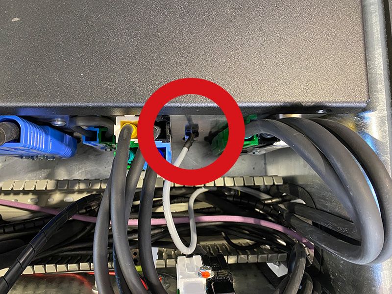
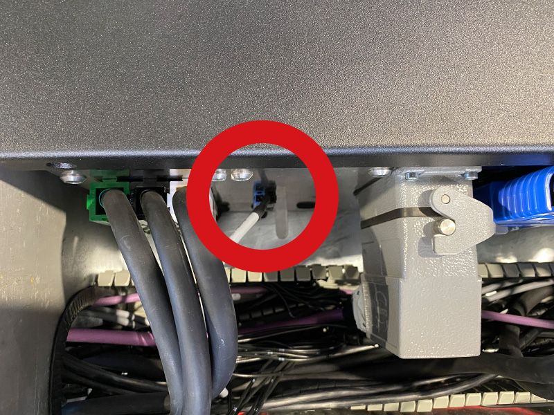
Remove the winch cover so that you can access the connections on the eCube. Now check the connector of the right magnetic brake. If it looks intact at first, remove the connector and check the contacts. Then restore the connection to the plug and see if the problem persists.
| Error Code | Description |
| 3-24 | No feedback from the right magnetic brake |
Troubleshooting
Remove the winch cover so that you can access the connections on the eCube. Now check the connector of the right magnetic brake. If it looks intact at first, remove the connector and check the contacts. Then restore the connection to the plug and see if the problem persists.
| Error Code | Description |
| 3-25 | No feedback from the right motor encoder |
Troubleshooting
Remove the right cover of the TF5 to gain access to the drive motor. Check the superseal connector and its pins on the cable going from the motor to the eCube.
| Error Code | Description |
| 3-26 | Temperature of the left drive motor 20°C above the limit value |
Troubleshooting
The first thing to determine is whether the tug makes unusual noises when driving? If this is the case, either a foreign object is blocking the motor or the tug’s magnetic brake is stuck and blocking smooth running.
If this is not the case, the temperature sensor may be affected. To do this, remove the left cover of the tug (under which the batteries are also located) so that there is access to the drive motor. From the motor a cable leads into a 6pin superseal connector. Check the individual contacts here to see if they are all intact.
| Error Code | Description |
| 3-27 | Temperature of the right drive system 5°C above the limit value |
Troubleshooting
| Error Code | Description |
| 3-28 | No feedback from the left magnetic brake |
Troubleshooting
Remove the winch cover so that you can access the connections on the eCube. Now check the connection of the plug of the left magnetic brake. If it looks intact at first, remove the connector and check the contacts. Then restore the connection to the plug and see if the problem persists.
| Error Code | Description |
| 3-29 | No feedback from the left motor encoder |
Troubleshooting
Remove the left cover of the TF5 to gain access to the drive motor. Check the superseal connector and its pins on the cable going from the motor to the eCube.
| Error Code | Description |
| 3-30 | Temperature of the turntable motor / winch is 5°C above the limit value |
Troubleshooting
Remove the left cover of the TF5 to gain access to the drive motor. Check the superseal connector and its pins on the cable going from the motor to the eCube.
| Error Code | Description |
| 4-1 | Battery voltage below limit |
Troubleshooting
First, the covers of the tug should be removed so that you can get access to the batteries. Now all batteries should be measured individually to see if all, or only individual batteries are below the limit. The battery voltage should not fall below 10.8V per battery (12V 200Ah), otherwise the batteries are considered defective.
If not all batteries are under voltage, but only one or some, the affected batteries must be charged individually.
If the value falls below 10.8V, and can not be restored when charge the affected batteries individually, the batteries are defective and must be replaced.
| Error Code | Description |
| 4-2 | Battery voltage of the radio remote control below limit value |
Troubleshooting
The battery of the radio remote control has an undervoltage. First, exchange them with the replacement battery, which is located in the front compartment of the tug and check if this caused the error.